| Embedded Microcontroller |
|
Raspberry PI I2C interface
Interested in the timing of the I2C signals on the raspberry pi? I was and could not find a good reference. So I decided to make up my own and hopefully help you to use the Raspberry PI I/O. I am a hardware guy, so I captured all of the i2c traffic and show not only the python software command, but what goes out on the wires.
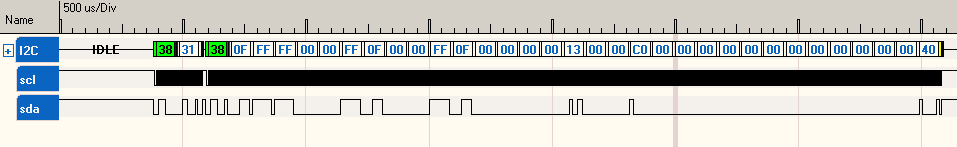
Running the "i2cdetect -y 1" command yields the following activity on the I2C bus:
Running the "i2cdetect -y 1" command yields the following activity on the I2C bus:
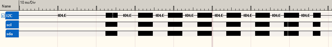
Raspberry PI I2C timing
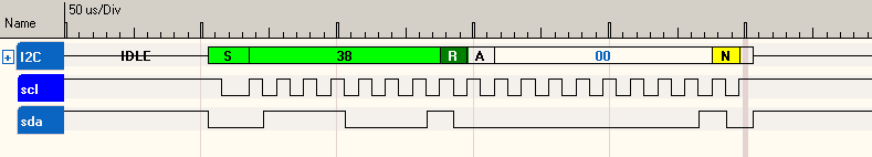
Now zooming in on the first "packet" of data:
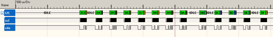
The "i2cdetect" command scans the first row of I2C addresses, starting with address "03" through "0F". Each group has a delay of roughly 5.5ms before the next group (of up to 16) of addresses is scanned. The scanning of all i2c addresses takes about 55 ms. The "i2cdetect" command basically sends a write to each i2c address on the bus. Any i2c devices connected to the bus are required to acknowledge the command by returning an "ack" bit.
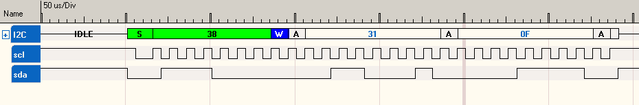
I have an active i2c device at address "0x38" attached to the bus. This next picture shows the device acknowledging the command:
I have an active i2c device at address "0x38" attached to the bus. This next picture shows the device acknowledging the command:
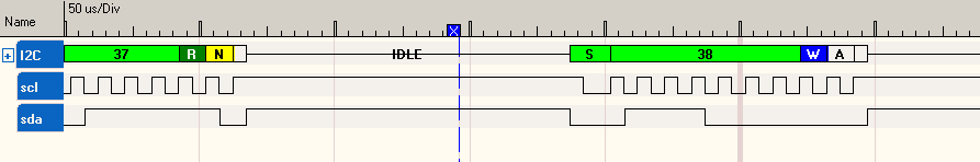
Raspberry PI I2C ACK/NACK waveform timing
The standard bit timing for the i2c waveform is 100 KHz, or 10 uS between bits. The time between the x and y cursors in the next diagram is 10 uS.
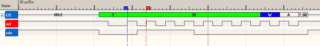
Raspberry PI I2C bit timing waveform
Raspberry PI I2C and Python
Now for some python controlling the i2c interface.
You have hopefully downloaded and installed the "smbus" library.
Note the first "bus" portion of the command is a variable that I picked with:
bus = smbus.SMBus(1)
You may use any variable you like.
You have hopefully downloaded and installed the "smbus" library.
Note the first "bus" portion of the command is a variable that I picked with:
bus = smbus.SMBus(1)
You may use any variable you like.
bus.read_byte(address)
This command will read one byte from the i2c device located at i2c (address). Now this command will work with a very simple i2c device. The waveform shows the address of the i2c device is first, followed by one byte of data which was read (output from i2c device). Waveform capture of bus.read_byte(address):
Raspberry PI executing a "bus.read_byte(address)" command
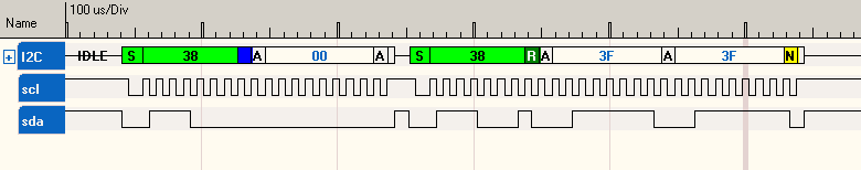
bus.read_byte_data(address,cmd)
Now in my experience the "cmd" is typically used as an internal address for the i2c to read the data from. Most i2c devices have several internal registers. The i2c protocol only specifies one single address for the entire device. Since all but the simplest devices require more than one 8-bit register, some form of sub-addressing is needed to read multiple registers. Unfortunately sub-addressing is not defined in the standard, so it is made up by the chip manufacturer. In the example below, I send "bus.read_byte_data(0x38,0x00)" to my i2c device. The raspberry pi formats an i2c write command back to back with single byte i2c read command. In my specific case data 0x3F was read from the i2c device internal address of 0x00.
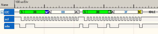
Raspberry PI executing "bus.read_byte_data(address,cmd)"
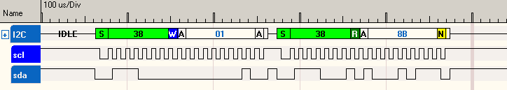
Here I sent "bus.read_byte_data(0x38,0x01)" to my i2c device. You can see that it reads back the data from its internal register 0x01 which happens to be 0x8B. You need to read the datasheet of the device that you are using to see how it wants to address internal registers.
bus.read_word_data(address,cmd)
Next up, "bus.read_word_data(address,cmd)". This command reads back two bytes at the specified address. The device that I am using auto-increments the read address, so the first byte back comes from local address 0x31 and the second byte read comes from address 0x32.
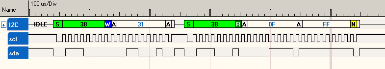
Raspberry PI executing "bus.read_word_data(address,cmd)"
If I attempt to read access the device at address 0x00, the internal local address does not auto-increment at this read address, so it will read back the same location (0x00) twice.
bus.read_i2c_block_data(address,cmd)
I sent the "bus.read_i2c_block_data(address,cmd)" command, which reads 32 bytes from the i2c device. The starting internal device address to read data from is 0x31, then 32 bytes are read out of the device, with the device auto-incrementing the internal read address on each i2c read.
Raspberry PI executing "bus.read_i2c_block_data(address,cmd)"
bus.write_byte_data(address,cmd,val)
Ok, now for the write commands. "bus.write_byte_data(address,cmd,val)" where address is the i2c address of the device, cmd is typically the local address of a location to write into, and val is the data to be written. So bus.write_byte_data(0x38,0x31,0x0F) says: write to i2c device at address 0x38, write to its internal register 0x31 the value of 0x0F.
Raspberry PI executing "bus.write_byte_data(address,cmd,val)"
bus.write_i2c_block_data(address,cmd,vals)
Use "bus.write_i2c_block_data(address,cmd,vals)" to write multiple values into the internal registers of your i2c device. The vals is a python list of contain bytes to send. Here I sent 0x01, 0x02, 0x03 to i2c address 0x38, internal register 0x31. The question I would ask now is: How many bytes can I send this way? Its 32 bytes, just like the read. So if you need to send more data, you have to break it into 32 byte chunks.

Raspberry PI executing "bus.write_i2c_block_data(address,cmd,vals)"
