| Embedded Microcontroller |
|
The Apple Disk ][ interface timing information.
Apple ][ Disk
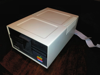
There is information available online on the Apple ][ disk interface, but it all appears to be somewhat incomplete to me. So here is the information that I believe is missing. I have captured these waveforms from a vintage Apple IIc computer. The IIc has a disk expansion port on the back where you can get easy access to the control signals. Since all of the control signals go to both the internal drive and the expansion external drive, it provides an easy method to snoop on real signals while using the internal drive. Schematics of the Disk II interface circuitry for the Apple II+ here.
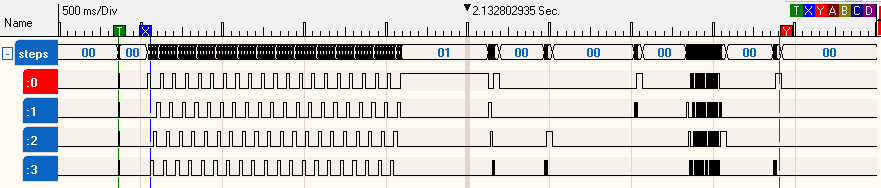
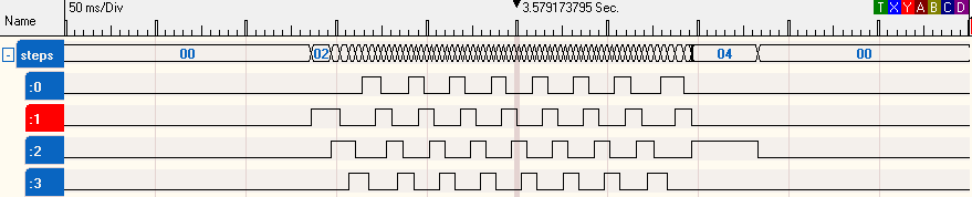
This first picture shows what happens when you first power on the Apple IIc with no floppy disk in the drive. The Apple IIc sends stepper signals to move the read/write head back to the home position. The overall time it takes to do this is 1.5 seconds. It should be noted that although there are 35 tracks on the disk, that the read/write head can actually be positioned over 70 tracks. Unfortunately with the tolerances involved, you cannot actually use 70 tracks. This is why you will later see the stepper mover being driven by two steps to move between each track.
This first picture shows what happens when you first power on the Apple IIc with no floppy disk in the drive. The Apple IIc sends stepper signals to move the read/write head back to the home position. The overall time it takes to do this is 1.5 seconds. It should be noted that although there are 35 tracks on the disk, that the read/write head can actually be positioned over 70 tracks. Unfortunately with the tolerances involved, you cannot actually use 70 tracks. This is why you will later see the stepper mover being driven by two steps to move between each track.
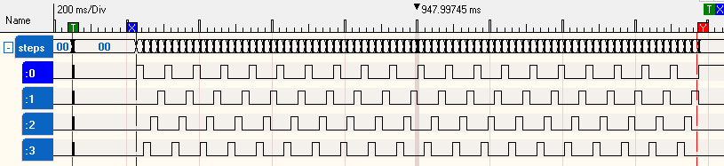
Apple Disk ][ stepper timing
The next picture is a close-up of a single pulse going to the drive stepper motor. All of the step pulses are the same duration. The step pulse is 19.3ms. I don't believe the timing is very critical.
Zoom in Apple Disk ][ timing pulses
Now it may look like the pulses are back-to-back, but this is not the case. There is a small "dead" gap time between pulses. The dead time is 14.7us. This picture shows the gap time. According to wikipedia this is "wave drive" i.e. one phase on. It is supposedly rarely used as the stepper motor will not generate full torque. I would guess that Apple did this for simplicity in that a very small piece of machine code is used to initialize the disk system. Later Apple uses the usual method for driving the stepper motor "full-step drive"
Stepper pulse GAP
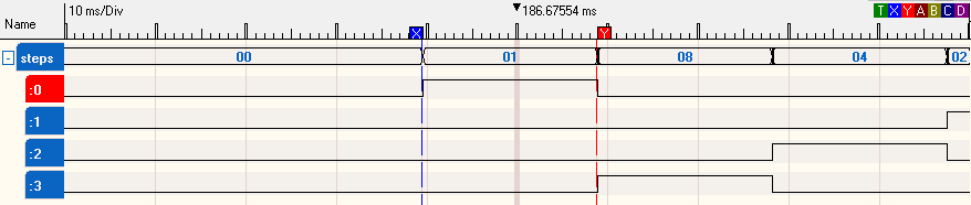
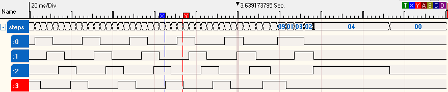
Next waveform is a capture of booting up DOS 3.3. The program that is automatically run at boot time is a very simple text print hello world. My DOS 3.3 disk is from 1983 (the hello world happened to have a creation date), which is booting fine in 2018 (35 years later). I have tried a number of these ancient disks and they have all worked so far. To decode whats happening a little help from the book "Beneath Apple DOS" is required. The Apple reads in sector 0, track 0 after the initial head positioning to track 0. Next sectors 1 through 9 are read in off of track 0. Up to this point there has been no need to move the disk arm. The next stage of booting moves the head to track 2, sector 4. It then reads in 26 more sectors, all the way down to track 0 sector A. Finally the "HELLO" program is run.
Overview of stepper during typical boot
So first up, move read/write head to track 2. Interesting that the stepper phases now overlap each other (its the full-step drive mentioned above). Line 1 pulse is 16ms. Line 2 pulse is 14ms. Line 3 pulse is 9.4ms. Line 1 to Line 2 overlap is 4.8ms. Line 2 to Line 3 overlap is also 4.8ms. Line 3 to Line 0 overlap is only 146us. Line 0 is then held high for 36ms.
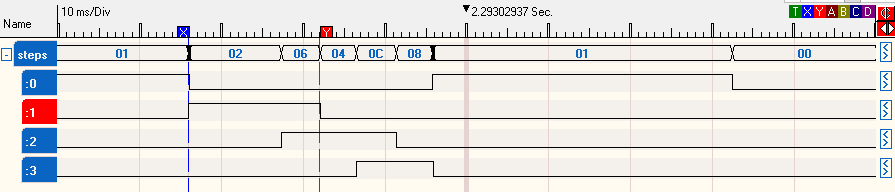
Zoom in of disk ][ stepper pulses
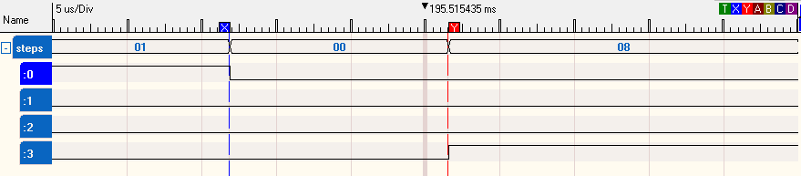
Next up move from track 2 to track 1. Line 3 pulse is 11.5 ms. Line 2 pulse is held for 36ms.
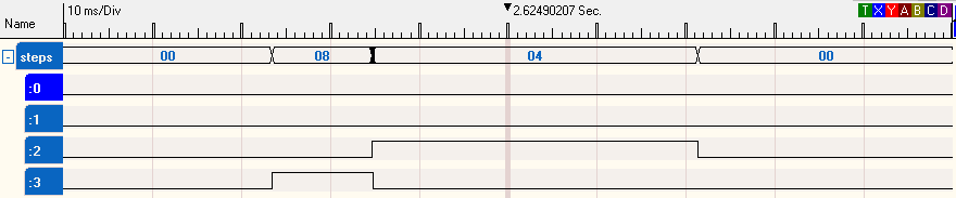
Stepping from track 2 to 1
Move to track 0. Hmm, looks just like the last one. Line 1 pulse is 11.5ms. Line 0 pulse is held for 36 ms. And yes there is 145us of overlap.
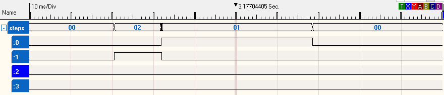
Stepping from track 1 to 0
Next up is run the HELLO program. DOS would need to move to track 17, where the catalog for the disk is stored.
Stepping out to track 17
Its interesting that the stepper pulses are now roughly 8.5ms with a 2.8ms overlap. The final pulse is still 36ms.
The Read Data stream
Now looking at the read data stream coming off the floppy disk drive. This is the actual signal on the read data signal. For some reason I thought I was going to see the data interleaved with the clocking bits. But I see this is not the case, as we see only the data and no clocking bits. The bit-to-bit timing is 4us. Each data bit is 1us in length. This capture is of an autosync pattern which is "1111111100". This pattern is used by the hardware to line up the data receiver with the first bit in a byte.
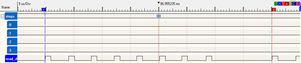
Read Data line from Apple disk ][, Autosync byte
Its hard to see, but if you look carefully, you can see that there are 13 autosync extended bytes before the valid data. Notice that the data appears random before and after the autosync extended bytes.
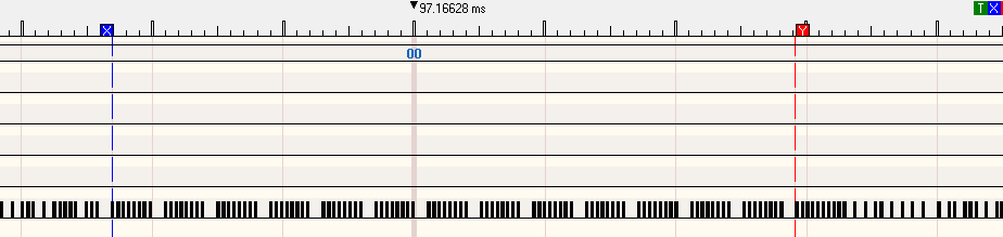
13 Autosync bytes
Now lets look at the data bytes that come after the autosync group. Not sure why the FF is there, but D5,AA,96 is the prologue to an address field. The Apple ][ uses a unique sequence of bytes to identify what type of data is about to be read by the machine.
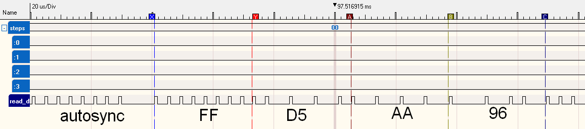
Apple disk ][ data following the autosync bytes
Read data synchronization and edge detect
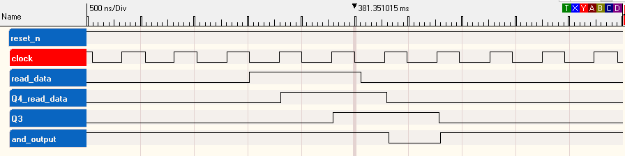
This picture shows the read data, being synchronized with a 2MHz? clock (I have seen it labelled as a 2MHz clock) and then sent to a falling edge detector circuit. This function is performed on the Apple II disk I/O card. The measured clock is 4.08MHz (490ns) rising edge to rising edge. High for 210ns and low for 280ns (forgive the granularity of my cheap USB logic analyzer). The read data pulses are 1uS. Q4 has the read data synchronized to the Apple II clock. Q3 is the same as Q4, but delayed by one clock cycle. The NAND output is a combination of Q4_read_data inverted and Q3, these give a low pulse for every falling edge detected on the read data stream from the disk drive.
Apple II Disk II reading, synchronizing, edge detecting
Here are several bits being read, synchronized, and edge detected.
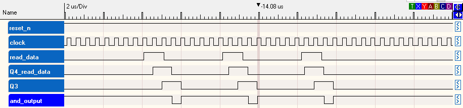
Apple II Disk II reading several bits
